Optical Phase Demodulators
Optical Interleavers
Tunable Optical Filters
Optical Monitors
 
Optical Channel Monitor
Optical Performance Monitor
Portable Spectrum Analyzer
Optical Wavelength Meter
   
Integrated High-Speed Receivers
Optical Test & Measurement
Optical Spectrum Analyzers
Lasers and Light Source
F-P Etalons Products
Custom-Design Products
Home > Products > Optical Monitors > Optical Performance Monitor
Optical Performance Monitor  
 
Optoplex Optical Performance Monitor
   
PDF Datasheet
 
  • Description
  • Features
  • Applications
  • Specification
  • Typical Performance
  • Parameter Definition
Product Description - Optical Performance Monitor

Optoplex Optical performance monitor (OPM) uses proprietary thin-film interference filter technology combined with a micro-actuator and high-speed electronics. Optical performance monitor is used to measure critical information data on optical transmission signals in DWDM networks for monitoring signal dynamics, determining system functionality, identifying performance change, and providing feedback for controlling network elements so as to optimize operational performance. In particular, Optoplex Optical performance monitor can automatically scan the C-, L- or C+L-band wavelength range and precisely measure channel wavelength and power. See the following schematic diagram for OPM working principle.

Working principle of Optoplex optical performance monitor

Operating through a continuous wavelength scan and built-in wavelength reference with optical tunable filter technology, Optoplex's Optical performance monitor has a high wavelength accuracy and resolution with a low channel cross-talk. Built with Optoplex's high-isolation and wide passband thin-film filter and assembled together with high-grade single detector, Optoplex's Optical performance monitor increases channel power measurement accuracy and dynamic range. Further, the Optical performance monitor includes a built-in filter driver and PCB to control and interface with all data-processing electronics. DPRAM, RS-232, or USB interfaces are available and can be customized to meet specific requirements. Optoplex's Optical performance monitor has passed Telcardia GR-468-CORE tests. Moreover, the Optical performance monitor device features compact size and low cost.

For Optical channel monitor, please visit OCM page.

Features and Benefits of Optical Performance Monitor
  • High Dynamic Range
  • Low Temperature Sensitivity
  • High Reliability and Repeatability
  • High Power and Wavelength Accuracy
  • Built-in Wavelength Reference
  • Compact Size
  • Firmware Upgradeable
  • 25 GHz and 33 GHz Channel Spacing Available
  • Copackaged 2-in-1 OPM available (2-port OPM)
  • Telcordia GR-468 Qualified
2-Port OPM
Applications of Optical Channel Monitor
Standard Specifications of Optical Channel Monitor1

Parameter

Unit

100 GHz

50 GHz

Wavelength Range nm C band or L band
Channel Number - 43 85
Adjacent Channel Power Difference dB < 13
Non-adjacent Channel Power Difference dB < 20
Minimum Spacing Between Channels GHz 75 40
Channel Input Power Range dBm -40 to -10
Absolute Channel Power Accuracy dB ± 0.5
Relative Channel Power Accuracy dB ± 0.3
Power Measurement Repeatability dB ± 0.1
PDL dB < 0.3
Absolute Wavelength Accuracy pm ± 50
Relative Wavelength Accuracy pm ± 30
Channel Wavelength Resolution pm 40
OSNR2 dB > 28 > 25
OSNR Accuracy2 dB ± 1.5
Noise Floor dBm - 55
Response Time ms 500 (Wavelength and Power)
1000 (Wavelength, Power & OSNR)
Power Consumption W < 2
Electronics Interface - RS232/DPRAM
Operating Temperature °C -5 to 65
Storage Temperature °C -40 to 85
Dimension3 mm 100x70x17.5 (Compact)
220x110x22 (Custom)

Notes:

  1. Certain parameter specs can be varied based on customer demands.
  2. Optional feature. Its values at lower input power level are limited by noise floor.
  3. Including PCB.
Typical Performance of Optical Channel Monitor

Typical performance of Optoplex optical performance monitor

Parameter Definition of Optical Performance Monitor

Parameter Definition

Example

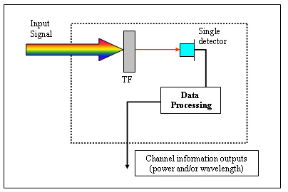
Wavelength Range (nm) is defined as wavelength range over which the Optical Performance Monitor (OPM) or Optical Channel Monitor (OCM) can measure the power and wavelength of the optical channels.

1530.33 - 1563.05 nm

Channel Number is the total number of channels defined in a channel plan that the OPM / OCM can identify.

42

Channel Spacing (GHz) is the equal frequency separation between two neighboring channels in DWDM system.

100 GHz

Input Wavelength Tolerance (GHz) defines the maximally allowed deviation of input laser away from ITU grid or channel plan. This parameter defines the minimum channel spacing. For example, for Input wavelength tolerance = ±5 GHz, channel spacing = 50 GHz, the minimum channel spacing will be 40 GHz in the worst case.

±5 GHz

Adjacent Channel Power Difference (dB) is maximum power difference between any two adjacent channels

12 dB

Non-adjacent Channel Power Difference (dB) is maximum power difference between any two non-adjacent channels

20 dB

Maximum Input Power (dBm) is total input optical power of all channels that is allowed to the OPM.

23 dBm

Channel Input Power Range (dBm) is the measurement power range of each channel when power and wavelength can be correctly reported.

-40 to -10 dBm

Absolute Channel Power Accuracy (dB) is defined as ±Max (|DPi|) over all the channels and operating temperature range, where DPi is the power measurement error against a calibrated power meter for the channel i.

± 0.5 dB

Relative Channel Power Accuracy (dB) is defined as the difference between the maximum and the minimum values of the power measurement error data across Spectral Range (all channels) at a measurement temperature. The worst-case value over all temperatures is used to specify Relative Channel Power Accuracy.

0.6 dB

Power Measurement Repeatability (dB) is the variation of a channel power measurement on a 1-minute interval at fixed peak power and polarization and at a constant temperature.

± 0.1 dB

PDL (dB) is the power difference between the two extreme polarization states.

0.3 dB

Absolute Wavelength Accuracy (pm) is defined as ±Max (|Dli|) over all the channels and operating temperature range, where Dli is the wavelength measurement error against a calibrated wavelength meter for the channel i.

± 50 pm

Relative Wavelength Accuracy (pm) is defined as the difference between the maximum and the minimum values of the wavelength measurement error data across Spectral Range (all channels) at a measurement temperature. The worst-case value over all temperatures is used to specify Relative Wavelength Accuracy.

60 pm

OSNR (dB) is measured as the ratio of a coherent signal power to a band-limited broadband noise source, normalized to 0.1-nm spectral window.

28 dB

Maximum OSNR (dB) is the highest OSNR that can be measured and still meet the OSNR accuracy and repeatability requirements. Its value depends on the input channel power level, noise floor, and filter isolation. See a typical example in the graph.

28 dB

OSNR Range is the maximum and minimum OSNR values, within which OPM can report OSNR with OSNR error < OSNR Accuracy.

10 ~ 25 dB

OSNR Accuracy (dB) is defined as ±Max (|DOSNRi|) over all the channels and operating temperature range, where DOSNRi is the OSNR measurement error against a calibrated Optical Spectrum Analyzer for the channel i.

± 1.5 dB

Noise Floor (dBm) is defined as electronics noise without light input.

-60 dBm

Optical Return Loss (dB) is the ratio between the input power and the reflected power over all polarization states at each port, RL = -10×log10(Pr/Pin).

40 dB

Response Time (ms) is the time required to perform the measurements of OSNR, power, and wavelength for all channels and transfer these values over the communications interface to the central controller.

500 ms

Power Consumption (W) is defined as peak electrical power when the OPM operates.

2 W

Operating Temperature (°C) is the ambient temperature range over which the device can be operated and maintain its specifications.

-5 to 65 °C

Storage Temperature (°C) is the ambient temperature range over which the device can be stored without damage and can be operated over operating temperature according to its specifications.

-40 to 85 °C

Product Request and Ordering Information
Please speak to Optoplex Sales persons. If you request custom-designed OPM product, please provide the following parameters:
  • Wavelength range
  • Channel spacing
  • Wavelength accuracy
  • Power accuracy
  • Fiber length
  • Optical connector type
  • Electrical interface